| HOME | Final L Section | N E X T ››› |
VIDEO [2.90 MB] Video not run?
It is assume that 'GL' sheet is complete.
Go to AutoCAD. Open new blank file. Give 'Lsec' command or select 'Lsec' from 'CSx' menu again.
This dialog box will display:
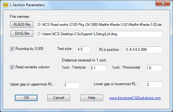
This time 'Roundup by 0.005' and 'Read Remarks Column' are ON.
Browse the DWG file used in left side of L section:

This is the DWG file we used:
You can select different file from 'CSxSupport' folder or any other folder.
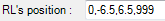
Here 0 is for center RLs, -6.5 is for left end and 6.5 is for right side end of OGL RLs. 999 symbol is for top RLs.
After giving all parameters, select 'OK' button.
After few seconds following prompts will display in command prompt area:
Give Range for L section (????-????) <ALL>: Press enter for all.
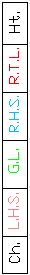
A DWG block (shown above) will display in drawing area, and following messages will display in command prompt:
Pick point for chainages or 'Enter': Pick near 'Ch.' in drawing area.
Pick point for (0.000) RLs or 'Enter': Pick near 'G.L.'
Pick point for (-6.500) RLs or 'Enter': Pick near 'L.H.S.'
Pick point for (6.500) RLs or 'Enter': Pick near 'R.H.S.'
Pick point for (999) RLs or 'Enter': Pick near 'R.T.L.'.
After picking all points, we will get L section as shown below. Delete RTL values.
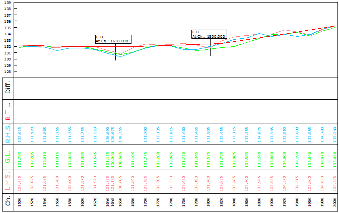
Top Next