| HOME | Heading Sheet | N E X T ››› |
Note that some parameters are not required in earth work cross sections, like 'ArLftRit', 'DrainOnlyInCutting', 'PCCarea', 'ExcaFromGL' and 'ConstantSlope'. These are used in multi layer cross sections.
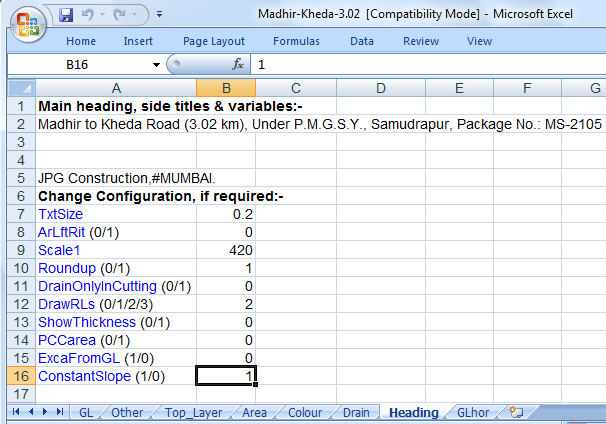
Cell 'A2' for main heading of drawing. Cells 'A3', 'A4' and 'A5'
are for side titles in right side. See the roll of '#' in cell 'A5'
(used for new line):
TxtSize: Height of text in drawing.
ArLftRit (0/1): Give '1' for separate areas of left and right side.
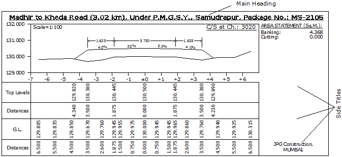
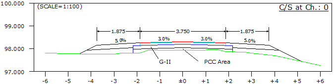
Scale1: To display scale in upper left side of cross section. For example, if you give '100', then 'Scale=1:100' will display. If you give '50', then 'Scale=1:50' will display. Give 420 for nothing. See above fig.
Roundup (0/1): Give '1' to roundup RLs by 0.005m. '200.543' becomes '200.545'.
DrainOnlyInCutting (1/0): Give '1', if you want drain only in cutting, because some time, one toe is in banking but another toe is in cutting.
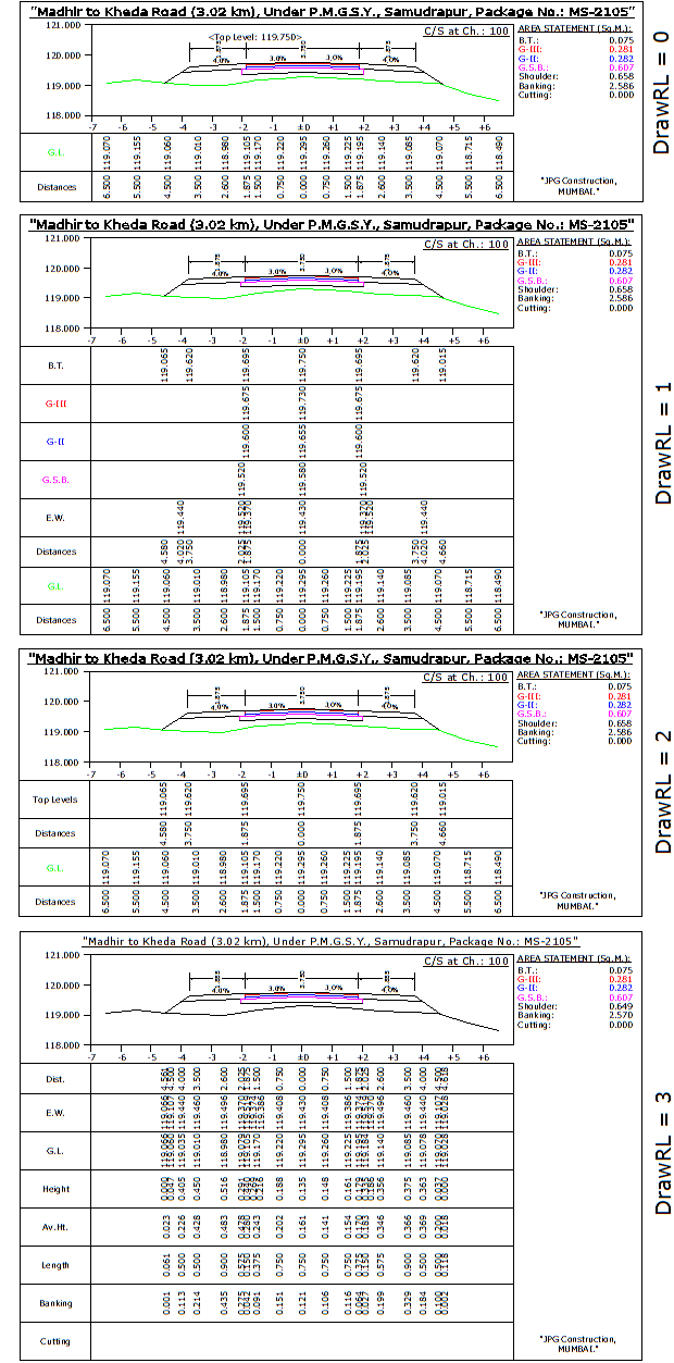
DrawRLs (0/1/2/3): When '0', only GL's distances and RLs will display. When '1', all layer's distances and RLs will display.
When '2', topmost layer and GL's distances and RLs will display. Give '3' for area calculation table within drawing.
Compare following four cross sections:
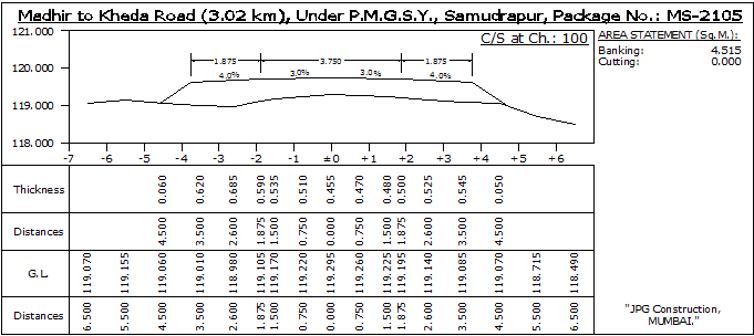
ShowThickness (0/1): Works only when 'DrawRLs' is set to 1, in simple following type of cross sections.
Thickness will show instead of RLs.:
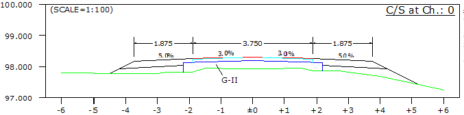
PCCarea (1/0): This is for Profile Corrective Course area. When value is 1, then PCC area is shown separately in area statement. This area is the area between 'PCC' line and ground profile. When value is set to 0, then it's area is added in lower most layer and hence does not show the area separately. PCC area works only when road is not a new road. For this, value must be 0 in second column of 'Top_Layer' sheet of data file. PCC layer also effect by 'ExcaFromGL (1/0)', explained in next parameter.
When PCCarea=1:
When PCCarea=0:
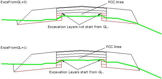
ExcaFromGL (1/0): This parameter required only when widening/excavation layers are also present.
If 1, excavation layers will starts from GL. Give 0, if you want widening layers to start from 'PCC' line.
Compare following two cross sections, how PCCarea also effects with 'ExcaFromGL' is set to 1 or 0:
Note that if only widening layers are present with no top layers, then this value is automatically set to 1, even if you give 0.
ConstantSlope (1/0): All top layers slope data are in 'Top_Layer' sheet and all widening layer slope data are present in 'Widening_Layer' sheet. Earth work slope data are present in 'Other sheet'. It is always difficult to manage slopes in three different sheets. Hence if you give '1' for 'ConstantSlope', then all layer's slope taken only from 'Other' sheet, columns: H, I, J and K. These four slopes are apply for all top layers, widening layers etc. If you give '0', then slopes given for every layer in different sheets will apply.
Value '1' is convenient.
Side Slope Cut (1/0): Give 1, to avoide 'V' shape in following type of cross sections. 'FL2' layer in 'Widening_Layer' sheet must present. Drains not allow in this mode. See the following figure: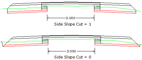
Top Next