| HOME | Road Plan |
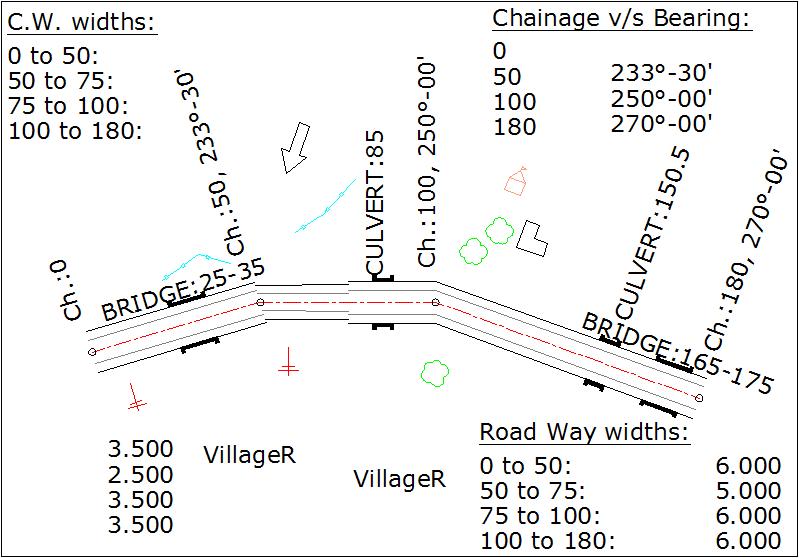
Following figure is generated by 'RP' command (by selecting 'RoadPlan' from 'CSx' menu):
Open new blank file in AutoCAD. Type 'RP' and press enter.
Following dialog box will display:
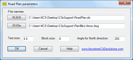
Click 'XLS(X)' button to browse your data file having 'RP' sheet. Sample XLS data file is present in 'CSxSupport' folder on 'Desktop'.
Click 'DWGs' button to browse a DWG file as a block used in drawing.
All required blocks (tree, house etc...) used in road plan are present in 'CSxSupport\PlanBlks' folder present on 'Desktop'.
Browse any One DWG file from these files.
Type '4.5' in 'Text size' edit box. This is the height of texts in drawing in Meters.
Type '8' in 'Block size' edit box. This is the size of all blocks in drawing in Meters.
Type '250' (or any value between 0 to 360 Degree) in 'Angle for North direction' edit box.
Click 'OK' button.
After few seconds following prompts will display in command prompt:
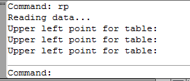
Upper left point for table: Pick a point in blank area of drawing.
Upper left point for table: Pick a point in blank area of drawing.
Upper left point for table: Pick a point in blank area of drawing.
Command:
Road plan is complete as shown above. Edit this drawing, if required and save the file.
Note the value '250' in 'Angle for North direction' edit box. This value is not fix and depending on given bearings in IInd row. Generally we want starting chainage in left side and ending chainage in right side. If you give other value for north direction then direction of drawing may not fit in paper size. In this case, open new blank file without saving this file and repeat 'RP' command and give different value for 'Angle of North direction'. This is 'trial and error' method.
Following is the XLS data for above road plan. Sheet name must be 'RP':
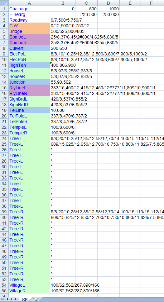
Give chainage and bearings in first two rows, in horizontal cells. Note that no bearing for first chainage because this is not required.
Roadway: Total of carriage way width and shoulder widths is called roadway width. In above shown data, this cell value is,
0/12,50/10,75/12
This data is in 'chainage/width' format.
At '0' ch., width is '12'. At '50' ch., width is '10'. At '75' ch., width is '12'.
C.W.: Called as carriageway width. Same as 'Roadway' parameter.
Bridge: This data is in 'starting chainage/ending chainage' format.
In above shown data, this cell value is,
25/35,165/175
1st bridge's starting ch. is '25' and ending chainage is '35',
2nd bridge's starting ch. is '165' and ending chainage is '175'.
'CompdL', 'CompdR', 'RlyLineL' and 'RlyLinR' cells have same colour in above data file and have same data format. All these item is explained by 'CompdL' item:
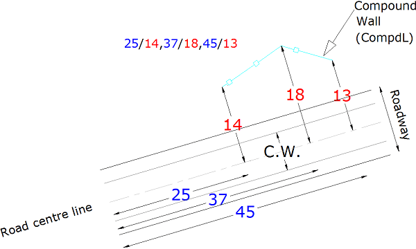
CompdL: Called as Compound wall in left side. Here cell value is,
25/14,37/18,45/13#60/20,68/25,77/35
Apply '#' for next compound wall data as separator.
This data is in 'chainage/perpendicular offset' format. Perpendicular offset is from centre line of road:
'Culvert', 'HighTen', 'Junction' and 'TelLine' cells have same colour in above data file and have same data format. All these items are explained by 'Culvert' item:
Culvert: Give chainages for culvert positions as in cell:
85,150.50
First culvert at ch. '85', next culvert at ch. '150.50'. Each chainage is separated by coma (,) symbol.
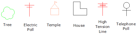
'ElecPoL', 'ElecPoR', 'HouseL', 'HouseR', 'SignBrdL', 'SignBrdR', 'TelPoleL', 'TelPoleR', 'TempleL', 'TempleR', 'Tree-L', 'Tree-R', 'VillageL' and 'VillageR' cells have same colour in above data file and have same data format. Only block symbols are differs. All these items are explained by 'ElecPoR' item:
ElecPoR: Called as electric poll in right side. Here cell value is,8/15,58/16
This data is in 'chainage/perpendicular offset' format, as 'CompdL' format. But '#' not required here. Each pole data is separated by coma (,) symbol. See above figure to get idea of chainage and perpendicular offsets from centre line.
Blocks used in road plan drawings:
Top